
HOME | TELESCOPES | KITS & PARTS | PRICING | CONTACT US | SCOPES AND TESTIMONIALS | FOR SALE | LINKS
If you have any questions, or see anything I haven't covered, please let me know and I'll add that information. Simply email me at densteele@dobstuff.com and I'll follow up and quickly as I can.
Call or email any time
tel: 650-315-6578
Thanks, Dennis

Collimation is easy, that is you just adjust the thumb screws without the need to "loosen two, tighten one"!! Easy.
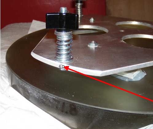
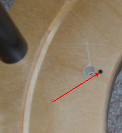
If I've installed your own mirror cell, it will still have a register. Usually on the "side" of the cell near one of the collimation bolts.
NOTE: Once the mirror and cell are installed onto the mirror board, tighten the thumb knobs until the springs are "FULLY COMPRESSED". Then, as you collimate the telescope, simply "release" some of the tension.
I like to use a 2" laser collimator and/or a collimating eyepiece.
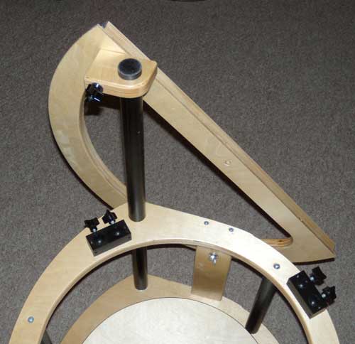
Slide the strut down through the hole and tighten. You may it a bit snug. Just "turn and push" until it's in place.
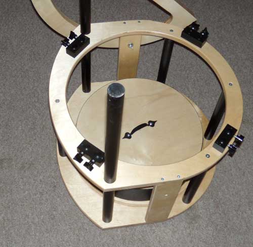
NOTE: During transport, you can leave the vertical struts into place. There is no need to remove them each time the telescope is dis-assembled.
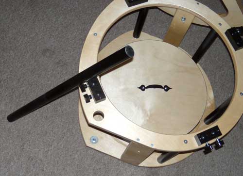
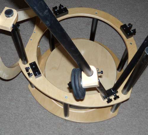
In this photo, the alt bearing is on the "left" side of the mirror box.
NOTE: Be sure that the "curved edge" of the clamp is on the inside and toward the CENTER of the primary.
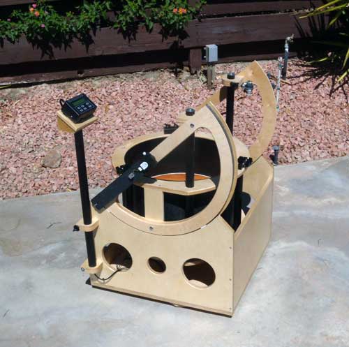
From here, you'll install the truss tubes and top ring or UTA.
NOTE: The way the telescopes are made, the top ring or UTA can be installed with the eyepiece on either side. I've built the scope so the focuser is on the "left" as seen from the rear.
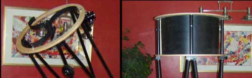
NOTE: Leave the thumb screws "loose" as you fit each of the truss tubes into the block. Then tighten "slightly". No need to over tighten -- just firm enough to avoid any slipping or movement.
For more information or help, call any time:
--Dennis Steele
--Tel: 650-315-6578 (anytime)
--Email: densteele@dobstuff.com
Copyright © 2007-2014 -- DobSTUFF.COM. All rights reserved